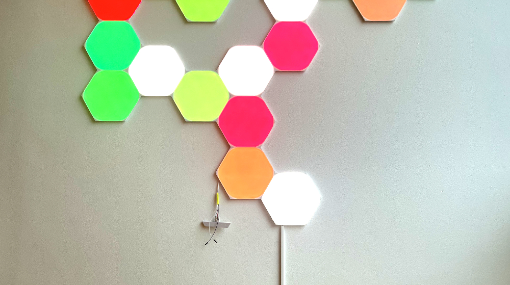
A large white wall at my house seemed to be the perfect canvas for Nanoleaf Shapes, combining functional lighting with an the possibly of making art, as you would be controlling each individual panel as large RGB-pixels. So I bought 30 panels and for the first couple of months everything just worked.
But then the issues started, which all seem to be related to the controller, which can be connected to the side of panels.
The app often failed to connect to the control the panels, the animations it played would pause at random intervals (which I suspect was related to something hanging on the controller side) and at one point, the controller just gave up. Nanoleaf was kind enough to replace the controller under warranty.
I am not sure Nanoleaf would offer a free replacement the next time the controller breaks (some people report that they have had theirs replaced several times). I like the panels and the life the lights bring to the room. So instead of the panels ending up as e-waste in case of controller issues, I have decided to reverse engineer how the panel communication works. This way, I would be possible for me or someone else to build an alternative controller.
The physical interface
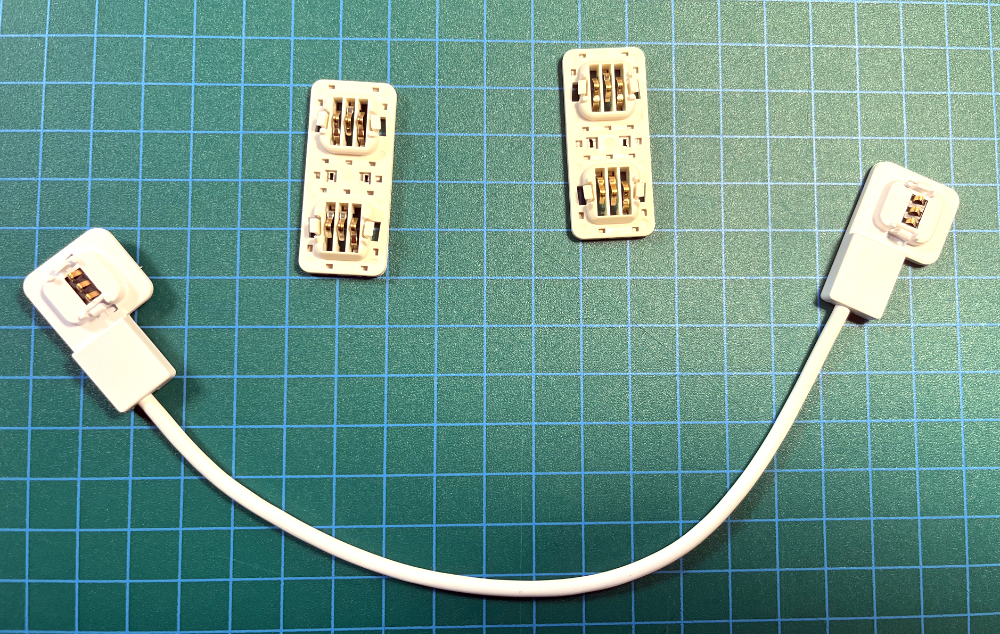
The panels, powersupplies and controllers all share the same three pin edge connector. The connector carries power and signalling. The panels (and controller) are interconnected by linker-tabs. Either the “short version” that allows for the panels to be installed flush to each other or the “long version” that allows for some distance between the panels. The latter can be useful if we want to move a home-built controller out of sight.
The three pins are as follows:
- Supply voltage, 42V
- Ground
- Data line, 3.3V level. Marked as ‘EDGE’ on controller PCB,
I expect that the connectors is designed to carry at least 75W (1.8A) of power (this is the beefiest power supply you can get).
The connector pins act as springs towards the mating connector, which is purely exposed pads on the PCB and locked into place to the molded plastic case. The PCB pad measures approximately 10mm x 1.5mm, with 1mm spacing between.
The digital interface
The controller and panels communicate over the half-duplex bi-directional data line. I have not dived into panel-to-panel communication, as the signal is relayed, but I expect this to follow the same characteristics.
Communication is UART 8N1 with an unusual 1Mbaud rate. All communication is initiated as commands from the controller, and any status/‘interrupts’ from the panels is raised through commands polling.
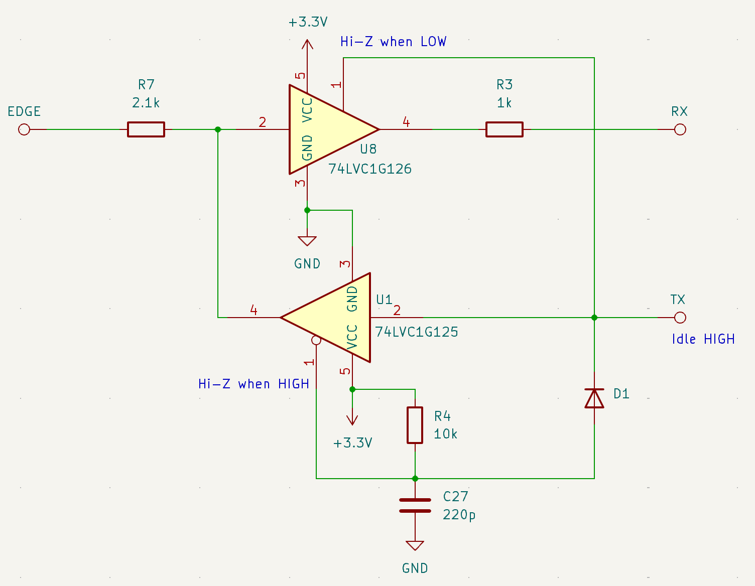
To enable this, a pair of tri-state buffers is connected to the EDGE connector, which are turned on and off from their Hi-Z state based on whether the TX has recently been toggled. This enables the EDGE pin to switch between RX and TX without having a seperate “direction” signal that would have to be syncronized to the UART.
High level protocol
The following commands have been identified from the sniffing on the wire and from symbols left in the firmware:
0x00‘Root side detect’ (I have not dived into this, but I expect this to be related to identifying where the controller is placed in relation the first panel)0x80Layout detection (request the panels to build out a tree of which panels are connected to them)0xE0Bulk push (used in animations to quickly update the color and brightness of all panels)0xC0Bulk pull (polling for ‘interrupts’ made by all panels)0xF8Commands for individually addressed panel, such as setting brightness and querying for panel versions and UIDs.0xFCCommands for all panels, such as setting overall brightness, enabling and adjusting touch sensitivity (yes the panels have a capacitive touch sensor) and keep-alive packets.0xFECommands related to panel firmware updates, including reboots.
Some of these commands I will expand upon below.
The general ‘boot sequence’ is as follows:
Detect layout → Query panel versions → Query panel UIDs
At this point the controller knows all that it needs to do, to start issuing bulk push with color and brightness to all panels. I see this mostly as a neat convenience function, as the layout of panels do not change that often and this can be mapped out by hand (once).
The panels and controllers support hot-swap. If a panel is hot-swapped in, the controller is smart enough only to interrogate the part of the tree that got affected.
Command 0x80: Layout Detection
The layout is detected by the controller sending a 0x80 on the edge connector. Then it reads the layout configuration until a 0x40 is received. It is clear that the firmware on the panels is doing the heavy lifting here.
The layout configuration consists is a long string describing each panel how it is connected to other panels and power supplies. Here is an example of such a layout configuration (in hex):
e5 00 e1 00 01 00 00 e4 00 01 00 00 01 95 00 e5 00 01 00 95 00 00
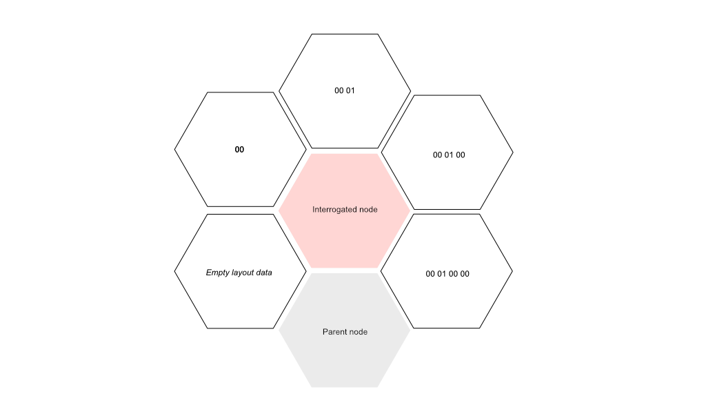
This string describes 6 nodes, 4 panels and 2 power supplies. Each node is prefixed with a one byte header describing the number of potential edges as well as its rotation, in relation to its ‘parent node’. A new node header can be identified by the fact that the highest bit have been set (mask 0x80). The header can be followed by 0 or more layout data bytes, which describes its relation to its parent. The order of each node also assigns the ID of that node. The interreogation is done based on a depth-first search, in case of a branching structure.
If we break down the layout configuration above into nodes:
e5 00 node id: 0 (based on order), number of edges: 6 (0xe5 >> 4 & 0x07), rotated to angle 5 (0xe5 & 0x0f)
e1 00 01 00 00, id: 1, edges: 6, angle 1
e4 00 01 00 00 01 id: 2, edges: 6, angle 4
95 00 id: 3, edges: 1, angle 5 (PSU)
and so on.
I am still working out the layout data portion (consisting of a string of either 00 or 01 bytes), but it is straight forward when there are no branches. Here the length of the layout data part is simply the difference in edge port number between the incoming and outgoing connected panel. A zero length string means that the node is connected next to the parent node (clock wise).
For hexagon shaped tiles, I have made the following obervations:
Any layout data string length that exceeds the number of edges - 2, indicates the end of the branch and provides a mechanism to return to a previously interrogated node and continue the tree search from there. I have not yet been able to figure out how that works yet.
Command 0xE0: Bulk push
Color and brightness data can be sent to all panels in a single command, this is useful for animations, where lower overhead is needed.
The command is prefixed by E0 03 followed by data for each panel, delimited into chunks which can be indexed based on the node ID. Each panel data chunk is variable in length depending on content. The firmware hints that E0 01 (8-bit colors) and E0 02 (16 bit colors) should be there as well, but it is not seen being issued by the controller.
05 [YY] [CC CC CC] [BB] is a command that sets color CC and brightness/on-off values BB. The role of YY has not yet been determined, but it could be transition speed.
If the panel should not be updated, the placeholder 01 FF can be used instead.
Command 0xC0: Bulk pull
The controller periodically asks all panels for any updates they might have. The two major reasons are touch input responses and hot-swap detection.
The controller starts the bulk pull by transmitting 0xC0 and then listens for a number of bytes equal to two times the number of panels. This means that each panel can transmit 2 bytes of data in their “time slot”. A value of 0xCC indicates that hot-swap was detected at this location, which causes the controller immediately to do layout detection.
In order to have the panels respond to touch, this must be enabled first by the 0xFC 0x07 0x01 command.
Command 0xF8: Command for individual panel
The individual addressing of panels requires the panel to acknowledge presence before the command is processed.
The controller starts by transmitting 0xF8 [ADDR_LOW] [ADDR_HIGH] [SUBCMD].
The address is encoded as 2 bytes, such that node ID 29 is encoded as 1C 00, and the sub-command is either 0x81 for querying version or 0x82 for querying UID. Other sub-commands exist in the firmware (such as 0x04 for setting brightness), but it is not seen on the wire.
Then bytes are read as 0x00 for each panel that the command passes through, and when the read byte turns to 0x01 the response of the command follows.
Here is an example of reading the verson of node 29, which is 8 nodes away from the controller:
Write: f81c0081
Read: 0000000000000001 06302e372e3000ffffffff322e332e30000000882b
The response includes the ASCII string 2.3.0 and 0.7.0.
Command 0xFC: Command for all panels
These commands are the simplest, since they go to all panels at the same time, no addressing or parsing needed.
Some of these commands include:
- Toggling touch sensitivity of panels:
0xFC 0x07 0x01and0xFC 0x07 0x00 - Setting brightness of all panels
0xFC 0x04 [BRIGHTNESS](0xFC 0x04 0x00to turn off) - Keep alive:
0xFC 0x08 0x00(I guess this is related to some watchdog in the panels)
Next steps
I hope this was helpful to get an overview of that the communication protocol looks like, and potentially inspire you contribute to my journey of getting a better controller for my Nanoleaf Shapes.
In the upcoming posts I will describe how you can extract and analyse the firmware, and dive into building the controller itself.
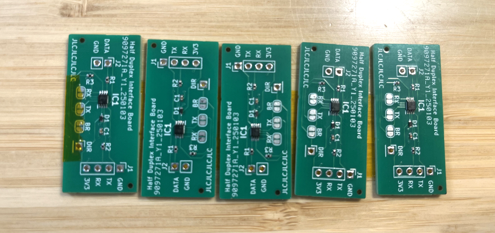
Teaser: The first batch of interface PCBs just arrived.