Here we go again. My Nanoleaf controller finally died, again. With the dark season setting in, a wall of 30 dark panels is not much fun, so getting an alternative controller working has moved up my list.
So I have picked up where I left off. In “Nanoleaf Shapes deepdive, part 1” I went through the protocol spoken between the Nanoleaf Shapes controller and the panels. One piece was left unsolved: how the layout detection (0x80) handles branches. I could decode a straight chain of panels, but as soon as the tree branched out, the “layout data” bytes stopped making sense.
Since then I have captured a lot more layout strings, while moving panels around, removing and inserting panels, rotating them and moving the controller. With those I now have a decoding that explains every capture I have, down to the last byte. This post is a short detour before part 2, to fix and complete the layout section of part 1.
Recap
The controller sends 0x80 on the edge connector and reads back a string of bytes until a 0x40 is received. The string describes a tree with the controller as the root, built by the panels doing a depth-first search. Every byte with the highest bit set (mask 0x80) is a node header, and everything else is what I called “layout data” in part 1.
The header byte, revisited
The upper half of the header still holds the number of edges of the node. Hexagons are 0xE_ (6 edges) and power supplies are 0x9_ (1 edge).
The lower bits are not really a “rotation”. They are the number of the edge on this panel that connects to its parent. Each panel numbers its own edges clockwise from 0 to 5, and the low bits say which of those edges the search arrived through. Once you know which of a panel’s edges faces its parent, its rotation follows, so the two descriptions are closely related. Thinking of it as an edge number is what makes the rest fall into place.
All my power supplies show up as 0x95. Since a power supply only has one edge, I don’t think the lower bits mean the same thing there.
Walking around the edges
The layout data does not belong to a single node. Every panel walks around its own edges, clockwise, starting with the edge right after the one facing its parent:
- If the next byte is a header, something is connected on the current edge. That node (and everything behind it) is described right here, after which we are back on the same edge.
- If the next byte is not a header, nothing more is connected on this edge, and we step to the next edge.
- When the next step would bring us back to the edge facing the parent, the panel is done. No byte is spent on this last step.
This means that a hexagon always contains exactly 4 (6 - 2) step bytes, but they don’t have to come in one piece. They can be split up by the panels connected to it, in the order they appear going clockwise.
Power supplies have no edges to walk, so they are just a header.
The example from part 1
Take the layout string from part 1 again:
e5 00 e1 00 01 00 00 e4 00 01 00 00 01 95 00 e5 00 01 00 95 00 00
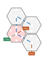
The example layout from part 1. Small grey numbers are the edge numbers of each panel, the red panel is the one connected to the controller.
The nesting is the key to reading the string. The bytes describing a panel are not in one piece, they wrap around everything connected to it:
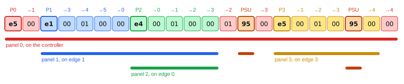
The example string, byte by byte. Each byte is coloured by the panel it belongs to. Above each byte is the panel a header starts, or the edge a step moves to. The bars underneath span the bytes describing a panel and everything connected behind it.
Decoding it:
e5: panel 0, the controller is on its edge 5. We start the walk on edge 0.00: nothing more on edge 0, step to edge 1.e1: a panel is connected on edge 1 of panel 0. This is panel 1, and it is connected through its own edge 1. Its walk starts on edge 2.00 01 00 00: four steps, bringing panel 1 around to edge 0.e4: panel 2 is connected on edge 0 of panel 1, through its own edge 4.00 01 00 00: four steps, and panel 2 is done, as the next step would take it back to edge 4.
- Panel 1 also has no steps left, so it is done as well.
01: back on panel 0, step to edge 2.95: a power supply on edge 2 of panel 0.00: step to edge 3.e5: panel 3 on edge 3 of panel 0, connected through its edge 5.00 01 00: three steps, to edge 3.95: a power supply on edge 3 of panel 3.00: the fourth step, panel 3 is done.
00: panel 0 steps to edge 4, which is its fourth step. Next would be edge 5 where the controller is, so panel 0 is done, and so is the string.
Every byte is accounted for. As power supplies do not get an ID, the last panel in the string is panel 3.
Revisiting the branch mystery
In part 1 I noted that “any layout data string length that exceeds the number of edges - 2, indicates the end of the branch”. Now it is clear why. The extra bytes don’t belong to that panel at all. When the last panel in a branch is done, the following step bytes belong to the panels further up the tree, which are continuing their walk where they left off.
The observations in the drawing from part 1 are just the number of steps a panel takes before reaching the edge where the next panel is connected: none for the edge right after the parent (clockwise), one for the next, and so on.
Checking against the real thing
The step bytes in my wall are always 00 01 00 00 for a panel. The firmware suggests that the second step byte is the shape of the panel, telling a hexagon (01) apart from other panels with 6 edges, such as the big triangle (02) and the Apex hexagon (03). With only hexagons on my wall I can’t confirm this on the wire. For walking the tree, their value doesn’t matter.
I decoded all 19 layout strings I have captured, and every single one ends exactly on the 0x40, with no bytes missing or left over. The full wall decodes to 30 panels, which matches the number of panels on my wall. If I remove a panel, the string gets 5 bytes shorter: one header and four steps.
Since every panel knows which of its edges faces its parent, and which of its edges each child is on, the tree can be drawn as hexagons on a grid, and it matches what is on my wall:

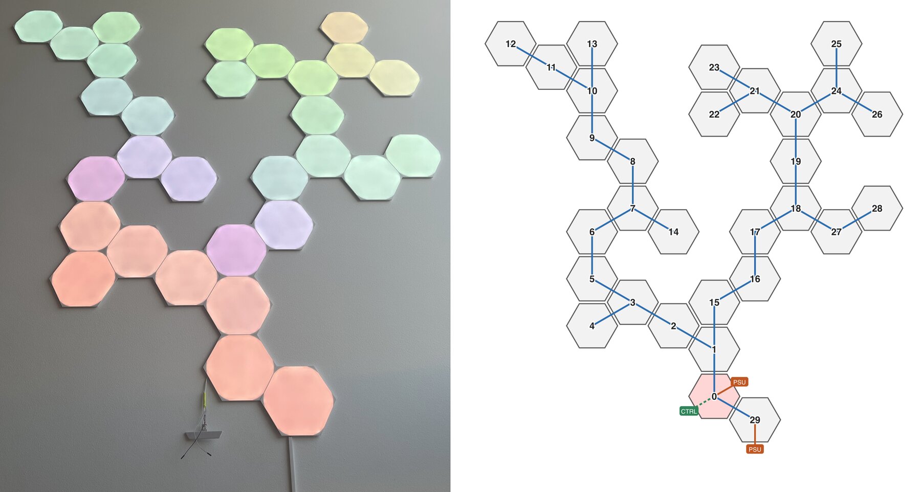
Left: the real thing. Right: my wall, drawn from a single layout detection string. Blue lines show the tree built by the depth-first search.
The panel holding the controller is panel 0, and the panel to its lower right is panel 29, with the power cable coming out of its bottom edge. From there the two arms of the tree can be followed all the way up to panels 12 and 13 on the left, and panels 25 and 26 on the right.
The tree doesn’t just follow which panels are next to each other, it follows the linkers. Two panels can sit right next to each other on the wall without being connected. To see this, I moved the linker going to panel 15 from panel 1 to panel 2, without moving any panels:
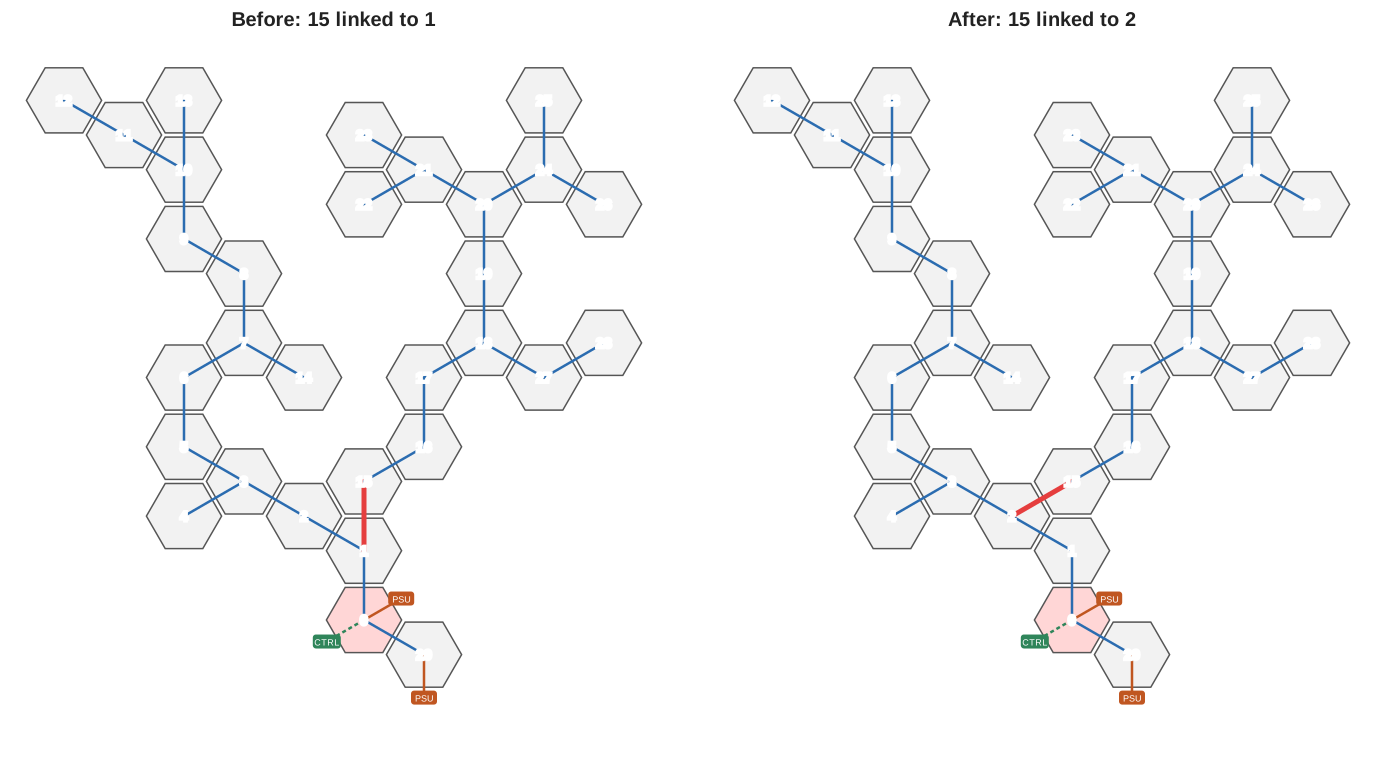
Moving a single linker further up the chain. The panels are in the same place, but panel 15 is now found through panel 2 instead of panel 1.
The panels stay where they are, but the tree changes: panel 15 is now one of panel 2’s children instead of panel 1’s. In the layout string, the 70 bytes describing panel 15 and everything behind it move from panel 1’s walk into panel 2’s:
  e5 00                                            # panel 0
- e2 00                                            # panel 1
+ e1 00                                            # panel 1, turned one edge
  e1 00 01                                         # panel 2
  e1 00 e1 00 01 00 00 01 e1 00 01 00 e2 00 01 00  # panels 3 to 14
  e2 00 e5 00 e0 00 01 00 e2 00 e0 00 01 e2 00 01
  00 00 00 00 01 e0 00 01 00 00 00 00 00 01 00 00
  01 00 e4 00 01 00 00 00 00 00 00 00
  00 00                                            # panel 2
- 01                                               # panel 1
- e0 00 01 00                                      # panel 15, via panel 1
+ e1 00 01                                         # panel 15, via panel 2
  e3 00 e2 00 01 00 e3 00 e2 00 01 e2 00 e4 00 e5  # panels 16 to 28
  00 01 00 00 01 e1 00 01 00 00 00 00 01 00 e5 00
  e2 00 01 00 00 01 00 e5 00 01 00 00 00 00 00 00
  01 00 e0 00 e2 00 01 00 00 01 00 00 00 00 01 00
  00
- 00                                               # panel 15
- 00 00                                            # panel 1
+ 00 00                                            # panel 15
+ 01 00 00                                         # panel 1
  01 95 00                                         # panel 0 and a PSU
  e5 00 01 00 95 00                                # panel 29 and a PSU
  00                                               # panel 0
  40                                               # end
The big blocks describing panels 3 to 14 and panels 16 to 28 are identical, as nothing changed in those parts of the tree. Only the bytes around them change:
- Panel 15 is now reached through a different edge, so its header changes from
e0toe1. Panel 16 is still on the same edge of panel 15, so panel 15 takes one step less before it, and one more after it. - Panel 1 no longer has panel 15 to visit, so its remaining steps (
01 00 00) all come after panel 2 is done. - Panel 1 also ended up turned one edge between the two captures, which changes its header from
e2toe1. This has nothing to do with the linker.
Notice that none of the IDs changed. Before, panel 1 found the whole branch from panel 2 to 14 first, and then panel 15. After, panel 2 finds the branch from panel 3 to 14 first, and then panel 15. Either way panel 15 is the next one found after panel 14.
That is luck rather than design. The IDs are just the order the panels are found in. Removing panel 4 shows what happens otherwise:
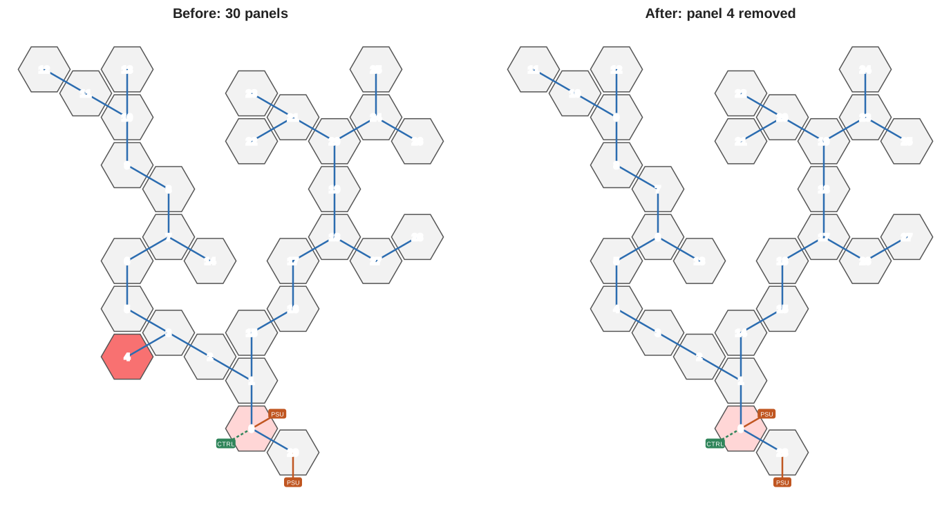
Removing panel 4. Panels 0 to 3 keep their IDs, every panel found after it moves down by one.
In the layout string, the change is just the 5 bytes describing panel 4, a header and four steps:
  e5 00 e2 00 e2 00 01 e0 00                       # panels 0 to 3
- e0 00 01 00 00                                   # panel 4
  01 e1 00 01 00 e2 00 01 00 e2 00 e5 00 e0 00 01  # panel 3, then panels 5 to 29
  ...
Yet panels 5 to 29 all get a new ID. To keep track of a panel over time, the UIDs (queried with 0xF8 ... 0x82) are a better handle.
Next steps
With this, the layout detection is understood well enough to replace the controller for my wall. A home-built controller can ask for the layout, draw it, and map each panel ID to its place on the wall, without any manual mapping.
There are still some open ends. I haven’t been able to confirm what the step bytes contain for other panel types like triangles or the Apex panels, and the 0x00 root side detect is still unexplored. If you have a Nanoleaf setup with other panel types and a logic analyzer, I would love to see your layout strings.
Next up, I will cover how to extract and analyse the firmware, and then move on to building the controller itself.